
Magneto Timing for Lincoln SA200 welders with Continental F162, 163 engines.
- maryann275
- 6 days ago
- 3 min read
It seems like every other question on these Lincoln SA200 forums concerns ignition timing. Everybody seems to have their own super special way of doing it. Let's see if we can start from the beginning and make sure everything is right, and you learn the easiest way to make it work every time. |
 |  |
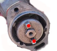
That's a fiber timing gear underneath the rotor. Remove the large cap. There are four mounting bolts that expose the fiber gear and the metal gear. The brown fiber gear turns the magneto rotor. At the time these were designed, we didn't have the plastics we have today, so these are fiber composites, and the teeth will break on them. The steel gear that turns the fiber gear should have a punch mark on the tooth that lines up with the fiber gear. The original Fairbanks-Morris did, but I see a lot of these cheap replacements out of China that do not. That's why we show you how to count the teeth. The steel gear with a punch mark on that tooth should go into the "C" slot. The letter C stands for clockwise rotation of the engine. The letter A denotes counter-clockwise or anti-clockwise rotation. This step is very important. Take your time and do it right. |
  |
If you're dealing with an engine that has been recently rebuilt, or if there's any doubt in your mind that someone has messed with the crank and cam gears, you're going to need to pull the front gear cover off. Note the timing marks on the crankshaft and cam gear in the image above on the left. There are two sets of marks. This engine will run either clockwise or counterclockwise. As shown in the image, this crankshaft is set up to run clockwise, as in all SA200s. |
If the engine has run before, then let us assume that these two gears are timed correctly. |
Removed the magneto so that you can see the governor gear and the cam gear, as shown in the image on the right. Remove all the spark plugs, and you can turn the engine over by hand. Rotate the engine until the two marks on the governor and the single mark on the cam gear line up and stop right there. Now the engine is ready to be timed, and at this point, the fourth cylinder is at top dead center on a compression/ignition stroke. |
Before we start the magneto, the first thing you need to do is remove the cap with the two small screws. Now you can see the rotor. On the back of the Magneto, there is a metal coupler with two tabs. These tabs mate with the two grooves on the Magneto's governor gear. On the coupler, turn the coupler tabs counter-clockwise until they mate with the governor gear. Install a new magneto gasket and stab the governor. There's one bolt on top that will thread through and catch in the magneto housing. Then there's a solid bolt at the bottom that goes all the way through to the front of the engine. Snug these bolts up. |
 | 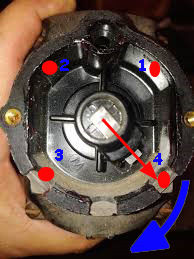 |
If you do this, it will help you avoid confusion. The image in the upper-right square is of the C800 distributor cap from the back. As indicated by the red arrow, that terminal is number four. Flip it over, and number four is in the 8:00 position. With a white permanent pen, put four little dots there at 8:00. On the ten o'clock terminal, put three little dots. On the two o'clock terminal: put two little dots on the 4 o'clock terminal, put one dot. When you reinstall the cap, you'll have no doubt of which spark plug wire goes to which terminal. Remember, the rotor turns clockwise on the magneto. |

Comments