
Continental F-162,163 Engine Distributor Timing
- maryann275
- Jun 8
- 3 min read
It seems like every other question on these Lincoln SA200 forums concerns ignition timing. Everybody seems to have their own super special way of doing it. Let's see if we can start from the beginning and make sure everything is right, and you learn the easiest way to make it work every time. |  |
 |  |
If you're dealing with an engine that has been recently rebuilt, or if there's any doubt in your mind that someone has messed with the crank and cam gears, you're going to need to pull the front gear cover off. Note the timing marks on the crankshaft and cam gear in the image above on the left. There are two sets of marks. This engine will run either clockwise or counterclockwise. As shown in the image, this crankshaft is set up to run clockwise, as in all SA200s. |
If the engine has run before, then let us assume that these two gears are timed correctly. |
Removed the magneto so that you can see the governor gear and the cam gear, as shown in the image on the right. Remove all the spark plugs, and you can turn the engine over by hand. Rotate the engine until the two marks on the governor and the single mark on the cam gear line up and stop right there. Now the engine is ready to be timed, and at this point, number four cylinder is at top dead center on a compression/ignition stroke. The original trick of putting your finger over the spark plug hole on the number one cylinder to check for pressure can lead you in the wrong direction. You're feeling pressure, but are you feeling pressure on a compression stroke or on an exhaust stroke? You need to identify a cylinder on a compression stroke; there's a reason Continental put these timing marks on this engine. Remember, this engine came to market in 1929 and is designed to run either clockwise or counterclockwise. |
The distributor pictured on the right is an original Prestolite IBT-4701. Many years ago, I purchased 2,000 of these Prestolites and converted them using the Pertronix electronic module. If you find one of these, buy it for one simple reason. If the world goes to hell and your module fails, you can drop a set of points in these and keep right on truckin'. Also, this mag is repairable. If the brass pushings on the inside wear out, they can be pressed out and replaced. | 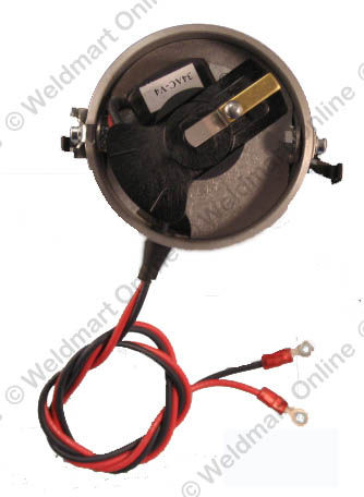 |
At the right is an exploded view of the Pertronix distributor. I feel it is very well engineered, having the module inside the dust cover with the rotor on top. These have a bad reputation for burning up the module. The problem is not the module. The problem is that people install cheap coils in their systems. You need a good coil with an internal resistance of at least 3 ohms. |  |
When you pull the cap off and look down, the rotor should turn in a counter-clockwise rotation, opposite of what a magneto turns. |  |
Before you try to install the distributor, first get a magic marker (something you can use to draw a distinctive line). Mark where each spark plug wire goes on the distributor, as shown in the image on the right. Now, once you remove the distributor cap, you have a pretty good idea of which terminal the rotor is pointing at. |  |
At this point, if the engine doesn't start or hit, you may have more trouble than you thought. I'll be glad to help you. Please call me at the number listed below or shoot me a quick email. |

Comments