
WE OFFER SOLUTIONS FOR YOUR MACHINE PROBLEMS
Come to us for more than just parts; we offer real help and information from a real, live person with experience. We are dedicated to going the extra mile to assist you.
The How and Why of the SA200 electronic (PC Board)
engine idler system.
With the introduction of the SA 200 K-6090 in the middle 1950's came the famous R-57 vacuum idler system. In my opinion, it was a testament to Lincoln's engineering team. Totally analog, a very simple system, but very limited for continuous pipe welding and prep work.


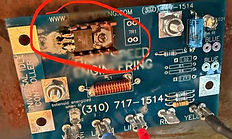
Latest Lincoln OEM Idler board Lincoln with sacrifical Transistor in Red Cheap copy of Lincoln
One of the most misunderstood systems on the Sa200 is the Electronic Idler (also known as the pc board idler). It is a very simple design. The idle solenoid has power on both terminals. One should come directly off the Low/High idle switch. When the idle selector switch is set to "High", 12 volts are applied to the far-right terminal, normally designated Y for the yellow wire. The other wire, normally white, connects to the last terminal, normally designated W.
When the board "Senses" demand for high speed, the little sacrificial $0.25 transistor turns on. The solenoid loses its "ground", releasing the plunger, and the governor speeds the engine up to "weld aspeed" controlled by the mechanical governor. Our Centaurion PC eliminates this problem with a 30-amp relay rated for 2 million cycles.

The system uses a "reed switch". A reed switch is a metal switch enclosed in a glass vacuum chamber. This is installed in the center of a spiral copper housing. When sufficient current flows through the switch, it closes, the contacts connect, and the board releases the idle solenoid, causing the machine to speed up.


How to check your Reed Switch:
The easiest way is with a test lead, connection the test lead to the Red terminal to a good ground, if the machine idles up, you only need a replacement reed switch. You can order one below.
The Lincoln idler PC board includes a secondary reed-switch board. All the current going out runs through the coil on the board. If the reed switch fails, you scrap the board.

Bare glass reed switch
Aftermarket reed switch assembly
The Lincoln PC board, and most of the cheap "knock-offs," use this flawed design. I have repaired many idle board failures by cleaning the ground connections. Sometimes I add a small ground wire from one of the mounting studs to the battery negative terminal on the governor. A large number of idle boards are replaced because of bad "ground connection".
Solve You Idle PC board Problem with the Centurion idler PC Board.

How do the LEDs make you self-sufficient?
LED # 2 is GREEN. As long as it is lighted the PC board has a 12 volts DC supply and a good ground. IT should never go out as long as the machine is running.b)
LED #1 is ORANGE. As long as it is lighted, the machine is in “Idle-Down” mode; the solenoid is pulled in, and the machine is at idle speed.c)
LED # 3 is RED As long as it is lighted the solenoid is pulled in and the machine is at idle.d)When LED #1 and #3 go off the idle board has sensed a demand to weld; the solenoid has released and the machine should be running at weld speed.e)When welding or auxiliary power is no longer required; a fifteen second delay occurs. The PC board pulls in the solenoid and the machine returns to idle speed.
How do You Test the PC Board?
Your idler isn't working. How can you test the board? The normal answer is buy a new one.
You can easily test the Centurion PC with a small magnet.
1. Jumper the oil pressure switch (you don't need to run the engine)
2. Make sure your idle switch is on Automatic.
3. If the GREEN and the Orange LED are lit up and the solenoid is pulled in, you know the solenoid and its
wiring are good.
4. Is the board defective? Run a magnet across the "Hall Effect" sensor block, in the lower right-hand corner, and the board should "Trip". You should see that the GREEN LED is lit. The ORANGE LED goes out, and the Red LED lights up. The solenoid releases in about 20 seconds, the board resets, and the solenoid retracts.
The board is designed to work with a conventional "Reed switch" or external sensing wire. Check your read switch and/or your sensing wires for connection. More instructions are included with the board installation paperwork.

If you appears to be defective, please call our office. Your board is warranted for three years from the date of shipment. We will fix it or replace it; you tell us what you want.
If it's out of warranty, you can return it for repairs. We would like to see it. We have had a few failures; the board has been on the market for over 12 years and has had very few issues. Most of the failures have been loose solder connections. Take it off and touch up all the solder connections with a soldering iron, waht do you have to lose?