
SA-200 Idler Troubleshooting
Overview:
The Lincoln® SA-200 idler system contains three main components; the failure of any one component will defeat the whole system. This guide explains how the Lincoln® idler system works.
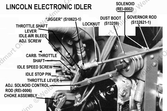
- The solenoid pulls the carburetor throttle plate closed and the engine drops to idle speed (1000 RPM or less). When the idle board senses demand to idle up, it opens up the ground side of the solenoid circuit, the solenoid releases, and the governor pulls the throttle plate open and maintains weld speed (1550 RPM no load and 1500 under load).
- The control PC board senses demand from the reed switch on the range switch (weld demand) or from the reed switch on the PC board (auxiliary power demand). The reed switch closes by magnetic flux. There is a transistor on the PC board acts like an electrical valve, open it up, and current flows; the solenoid pulls in. Turn it off (close it) and the solenoid releases; the welder idles up.
- There are two reed switches: one on the PC board and one externally mounted on the range switch.
- The reed switch on the PC board is wired in series with the auxiliary power circuit.
- The reed switch mounted in the copper strap on the range switch senses weld demand. When you strike an arc, the current concentrated by the spiral strap makes the reed switch close.
Quick Checks:
- The idler is dead; engine runs at high speed, but it will not idle down -- GO TO STEP A.
- The engine is held at low idle speed; the idler will not allow the engine to idle up to weld speed with a grinder or by striking an arc -- GO TO STEP H
- The idler will idle up with a grinder only, but will not idle up by striking an arc -- GO TO STEP X
- The idler idles up by striking an arc, but will not idle up with a grinder.
- The idler idles up, but drops back to idle too soon.
A: YOUR IDLER WON’T WORK -- HERE IS WHAT YOU NEED TO DO:
The idler is dead; won’t idle up or down with a grinder or by striking an arc.
Checking the idle solenoid-the oil pressure switch must be jumpered.
Take one of your test leads and put it across the oil pressure switch. This will power-up the engine electrical system and give the idle circuit 12 volts DC.
Pull the far right wire (normally white) and touch it to ground. If the idle solenoid and its wiring is good it should pull in fast and hard!
If the solenoid pulls in stop! The solenoid and the wiring are operational.
B: The solenoid does not pull in:
A) To troubleshoot the solenoid, first check it for mechanical restrictions; does it move back forth freely? If not find out why and fix it! I have seen the solenoid full of sand!
Note: Run these checks in the order I have them-they will save you time!
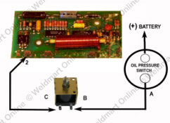
B) Connect the test light grounding clip to a good ground and check for 12 volts on one terminal of the oil pressure switch (this will be the HOT side). The opposite terminal should show no power. If it does show power-with the engine off, remove the wire and recheck the terminal. If it is still "hot"-replace the oil pressure switch.
C) Take one of the test leads and jumper the terminals on the oil pressure switch. This will "power-up" the idler system.
D) With your test light (with the machine NOT running), check for 12 volts on each terminal of the oil pressure switch. You should have the same voltage (the same brightness on the test light) on each terminal.
E) Remove the wire on Terminal 2 of the PC board and check wire the test light. If you have a "hot" wire-and the solenoid is not pulling in-replace the solenoid. If the wire is cold-go to Step (F).
F) Trace the white wire from Terminal 2 on the PC board back to where it connects to the solenoid. (Connection "C" on the illustration). Check the terminal C on the solenoid. IF it is hot the wire from Connection C (on the solenoid) to terminal C (on the PC board may be broken. If there is any doubt-replace it!
A. If there is any doubt about the solenoid, take the test leads and run one from the (+) terminal on the battery and the other to the (-). The solenoid must pull in with a sharp "SNAP"! With 12 volts on the solenoid, it will be very difficult to pull the plunger out by hand.
B. The idler solenoid is good but it will not idle up when you strike an arc, or when a grinder or light is attached.
Checking the idler-the oil pressure switch must be jumpered-the engine off!
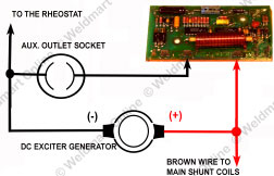
It is now time to check out the PC board-the Lincoln is notoriously fail prone (a new board only has a 90 Day Warranty!) Lincoln seems to be hell bent on putting as many components as they can cram on their PC board and charge as much as they can. Since the SA-200 is officially "obsolete" they really don’t care-its history. The graphic below can be used as quick guide to wiring the Lincoln PC board.
NOTE: Take one of your test leads and put it across the oil pressure switch. This will power-up the engine electrical system and give the idle circuit 12 volts DC.
# 1: There are two mounting bolts that attach the board to the front of the control panel. The board gets its electrical "ground" through these bolts. All electrical measurements should be made using one of these screws as "ground". One lead of the meter or test light clip should be grounded to a mounting screw.
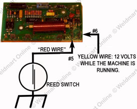
# 2: With the test light ground clip on one of the PC board grounding screw, check for 12 volts on Terminal #6 (Normally a Yellow wire). It should glow very brightly! You should see the same voltage (more-or less) as seen on the battery posts!
a) If the test light is bright-the board is getting 12 volts-GOOD!-REPLACE THE BOARD!
b) If there is no indication of 12 volts on the yellow wire, you must find out why before you continue. The board must have a good source of 12 volts to operate properly.
For a quick check; use one of the test leads and temporality apply 12 volts from any convenient source on the machine (find one with the test light!) to the far right terminal of the pc board-this will "power-up" the board-the solenoid will pull in. You now know the board and solenoid is probably working as it should-fix the problem with the yellow wire, start the machine and make sure the idler is now working.
J: The idler will not allow the engine to "idle-up" to weld speed.
At this point we know the idle solenoid is good, the PC board has a good ground, and there is 12 volts on terminal #6. The damn thing just won’t work!
- Plug in a grinder (it must be a universal motor –AC/DC) don’t use an AC grinder-you’ll fry it! When you trigger it the idler should release and the engine speeds up to weld speed (1500 RPM). If it does the board is most likely good. Go to step E.
- Remove the "Red" wire found on terminal #5 (this wire goes to the Reed Switch-mounted in a strap on the back of the range selector switch.)
- Connect one of the test leads to terminal #5 and touch it to ground. If the solenoid releases-replace the reed switch.
- If the solenoid does not release-replace the PC board.
K: The idler will not allow the engine to idle up when a grinder is used.
1. Plug in a grinder, if it runs at a slow speed, but the engine will not idle up-replace the PC board.
2. If the grinder is "dead", try another grinder that you know is good. Still nothing?
3. First you need to check the auxiliary outlet. If there is any doubt replace it
4. If this does not fix the problem, you have to check the wires.
Really Good Stuff to Know!
A. You Need a Test light.
A test light is one of the simplest and easiest to use electrical test instruments ever invented. It relies upon the ability human eye to discern minute differences in luminance.
Different voltages will cause changes in the test light’s brightness. The light will never take the place of a volt meter, but it is a quick, one handed troubleshooting tool.
If you take a few minutes and read these instructions, three very positive events will happen in your future.
One: You will have a better understanding of your welder’s engine electrical system.
Two: You will be able to better identify problems with the engine’s electrical system.
Three: You will not have to take time off the job and haul your machine to somebody you don’t know who is going to charge you $60.00 to $100.00 an hour to look at your machine!
This very simple tool is your first step to technological self-sufficiency!
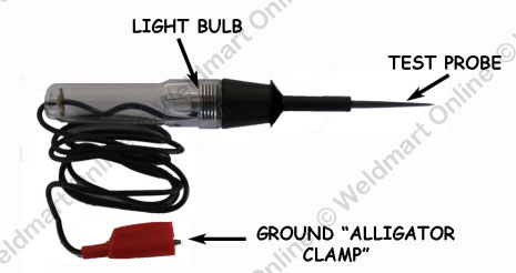
Your test light has one moving part; the ground clip.
B. You welder’s electrical system in a nutshell:
- The battery is the "storage tank" for the electrical power. It feeds electrical power (DC Voltage) to; the alternator (to jump start it), the starter motor to spin the engine, the electronic engine idler, the distributor (IF YOU DO NOT HAVE A MAGNETO IGNITION-A MAGNETO MAKES ITS OWN POWER), and the green "oil pressure light" if you have one-that is it!
Your test light will give a quick & dirty indication of what has voltage and where is it. - You can do a quick check to tell if it full (charged) by putting the test light across the terminals (polarity does not matter-this time). The light should glow very bright! Have someone crank the engine; the light should dim, but still be bright. If the light gets very dim or goes out this could be an indication that the battery is weak and your need to check the voltage with a meter.
Here is what you should see: - 12.6 volts battery is fully charged (you need to check the starter)
- 12.4 The battery is 75% Charged, after running the welder the alternator should bring it up in 20 to 30 minutes.
- 12.2 The battery is at 50% charge.
- 12.0 The batter is at 25% charge.
- 11.8 The battery is at 0%, you will have to have a "jumper battery" to use the electric starter.
- 10 volts indicated a bad cell-time for a new battery.
FYI (FOR YOUR INFORMATION)
62% OF ALL STARTER FAILURE ARE DUE TO WEAK BATTERIES! 19% OF ALL STARTER FAILURES ARE DUE BAD CABLES, CORRODED TERMANIALS AND GROUND STAPS!
It’s a good idea to check battery voltage and then see how bright the test light burns on fully charged and partially charged batteries.
The alternator (or generator) converts rotary power from the engine into DC current to charge the battery-that’s all!
Clip the alligator clip to a good ground (no rust, paint, grease, dirt, or shit!) and touch the probe (make sure your remove the safety shield) to each post of the battery.
One post will cause the light to burn (that is the POSITIVE POST); the other post is the NEGITIVE Post-no light!
With the test light clip connected securely to a "clean" ground; this picture shows you what you should see with your test light.
5. If the oil pressure switch is shorted (it will not open [turn off] when engine oil pressure drops to zero) both sides of the switch will be "hot" at all times! This should be confirmed with a continuity tester; remove all wires and check for continuity with the engine off! Replace as necessary.
6. Check your starter solenoid with the Test Light.
A] The large nut is the 12-volt lead directly from the battery to the starter solenoid. It should be "hot" at all times. Checking with the test light-it should be very bright all the time.
B] The wire attached to this stud (3/8" Nut) feed 12 volts to the starter solenoid when the starter push button is pushed. When the button is pushed the test light should be bright. If the test light does not glow-remove the wire from the solenoid and retest. If the wire is "hot" when the button is pushed and the solenoid does not engage-the starter needs repair.
C] This stud is where the solenoid feeds 12 volts to the starter motor when the solenoid is engaged. The test light should be bright when the starter push button is pushed. If the light is bright when the button is pushed and starter motor does not engage-the starter needs repair.
7. To check a wire to see if is "open" (broken internally) the test light will give you a positive test.
a) Disconnect the wire-both ends free.
b) Connect one of the test leads to the end of the wire you are testing.
c) Connect the other end of the test lead to a source of 12 volts (the battery is OK-attach it to the positive terminal.
d) Attach the test light alligator clamp to a good ground.
e) Touch the test light probe to the end of the wire; it should glow brightly. If the wire is good the light will glow very bright. If the light is dim-replace it!
f) Wiggle the wire if the light flickers-replace the wire. If you have any question-replace it!
Why a tube of Dielectric Grease?
The electrical system on your welder is exposed to the elements, water, dirt, grease, and whatever the environment throws at it. Combine this with vibration, heat, and cold—you’re going to have to do constant maintenance to keep it running reliably.
Use the grease to coat any exposed connection. Coat the inside of spark plug boots any electrical item that will benefit from protection form the environment!
C).UPGRADING YOUR IDLER PC BOARD
If you have a Lincoln OEM (Original Equipment Manufacture) idler PC board, the day is coming when it’s going to die. They normally die either right in the middle of a weld test or late on a Friday afternoon; when you have one more weld to finish, so you can get the inspector to sign off on it, and you can get paid! (Murphy’s Law strikes again!).
If you decide to buy a “generic idler board” whose board do you buy? How can you tell one board from another? What should you look for? What should you avoid? This section will give you good common sense ideas on what to buy, what to consider, and most importantly—what to stay far, far away from.
First item on the list is the board itself, Since we are most familiar with our own idle board-we will use it as the "standard".What ever PC board you buy there should have certain criteria the item should have; including the following:
- Who manufactured the PC board?-If there is no information-RUN!
- Is there contact information on the board? If there is no information-RUN!
- Is there a phone number that you can call; an 800 number? If there is no phone numbers-RUN!
- Is there any other contact information; fax number, email address, anything? If there is no additional contact information-RUN!
- Is there even a part number? How can you identify the part without a part number? If there are no part numbers-RUN!
- What is the warranty? Is the warranty voided if not installed by an authorized, certified technician?
Note: Replacement PC boards from Miller Electric must be installed and documented by a Miller certified technician. If this is completed the warranty on the replacement is Ninety Days! If the customer installs the Miller replacement PC board-all warranties are null and void (Sort of give you a warm, Miller blue, fuzzy, feeling-doesn’t it?)
7) Are there installation instructions (documentation) with the idler board? If there are no instructions -RUN! The seller should be willing to mail or email a copy of the installation instructions upon request.
8) Is there technical help available? Is it free or do you have to pay for technical assistance? If there is no technical support-RUN!
9) Is the PC board repairable? (Most new Miller and Lincoln PC boards are multi-layer/surface mounted technology or the are sealed in some type of potting plastic-making them impossible-or nearly impossible to repair) refer to line 6-the warm and fuzzy part. If it cannot be repaired-RUN!
What ever board you buy you are spending your hard earned money; don’t spend it foolishly. Invest your money wisely.