SA-250 Idler Upgrade Board Installation Instructions
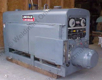
Weldmart-Online Universal Welder Idler Upgrade Board for Lincoln® SA-250 AC Exciter (Weldmart-Online part number WM2000)
Overview
Weldmart's Upgrade Idler Board Kit includes the following:- Upgrade PC Idler Board
- Tube of Dielectric Grease
- Hardware Mounting Kit
The Weldmart-OnlineUniversal Idler PC board is a direct upgrade replacement for all Lincoln® PC boards used on SA-250-3152 from code number 7827 thru 9605.
The Weldmart-OnlineUniversal Idler PC board replaces all Lincoln® PC board for these code numbers. It mounts in the same place with the same holes as the original PC board.
Along with the PC board is hardware to mount the PC board. It is important that the holes in the front panel are clean (bare metal); remove any and all paint and rust. Coat the clean surface with a small amount of Dielectric grease, which comes in the kit.
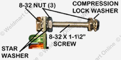
The biggest problem we have with the idler kit is poor or missing grounds. The PC board is grounded through the two mounting holes and through terminal #2. Two #8 x 1 ½" machine screws are included. Insert the screws through the holes and secure with the star lock washer and the nuts. Mount the second bolt on the screws and add another lock washer.
Coat the pads on both sides of the PC Idler board with a small amount of Dielectric grease. The board mounts on the bolts with star washers on both sides of the PC board. Do not over tighten: just make it tight enough that the washers make an impression in the solder pad.
NOTE: The back of the board cannot come into contact with the front panel of the welder!
The use of the star washers and the Dielectric grease assures a good secure mechanical and electrical ground connection. NOTE the sequence of the lock washers!

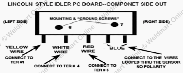
Lincoln-style PC Board Lead Connection:

Wiring:

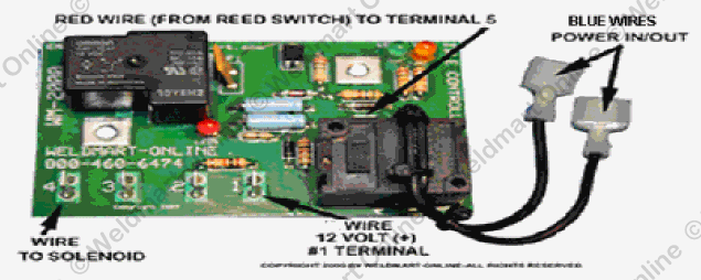
- Connect the YELLOW wire (12 VOLTS from idler switch) to terminal #1.
- Connect the WHITE wire (from solenoid) to terminal #4.
- Connect the RED wire (from the Reed-Switch) to terminal #5.
- Connect the TWO BLUE wires (auxiliary power sensing) to the Blue male terminals.
- The PC board gets its ground through the mounting bolts.
What do the LEDs tell you?
- LED #2 is GREEN. As long as it is lit, the PC board has a 12-volt DC supply and a good ground. It should never go out as long as the machine is running.
- LED #1 is ORANGE. As long as it is lit, the machine is in idle-down mode: the solenoid is pulled in and the machine is at idle speed.
- LED #3 is RED. As long as it is lit, the solenoid is pulled in and the machine is at idle.
- When LED #1 and #3 go OFF, then the idle board has sensed a demand to weld; the solenoid has released and the machine should be running at weld speed.
- When welding or auxiliary power is no longer required, a 15-second delay occurs. The PC board pulls in the solenoid and the machine returns to idle speed.
Troubleshooting the Weldmart-OnlinePC Board Installation:
- Using a meter or trouble light: you should have 12 volts DC between terminals 1 and 2 with the oil pressure switch terminals jumpered. If you do not have 12 volts across these two wires, go to step 2.
- Is terminal #1 getting 12 volts (+) and terminal #2 connected to a good ground connection?
- To check with a meter: Connect the Red (+) lead to terminal 1 (ONE) and the Black (-) to terminal 2 (two) on the PC board. The meter should read a minimum of 12 volts dc (if the meter pointer pegs to the left, reverse your leads!). If you are reading less than 12.1 volts--read the voltage at the battery terminals--you could have battery problems!
- To check with your Test Light: Connect the alligator clip to terminal 1 (one) and touch the probe to terminal 2 (two) on the PC board. The light should be very bright (the level of brightness as testing across the battery posts). If the light is "dim," check the brightness at the battery terminals--you could have battery problems! Check it with a meter (look at paragraph [a]).
- Check the ground connection; the PC board grounds thru the mounting screws. If further ground connection is needed an additional wire can be attached to terminal #2 to the negative side of the battery.
- A quick check of the sensor on the PC board can be made by jumpering terminal #5 to one of the grounding screws. Orange LED #2 and Red LED #3 will turn off and the solenoid will release (the machine will idle "UP").
- If the board is good, the solenoid will pull in and stay in. If you have 12 volts coming into the PC board, a good solenoid, and proper wiring to the solenoid and the board does not release the solenoid: Replace it.
- The unit will not idle up when auxiliary power is required.
If the welder idles up OK for welding but not for auxiliary power, there can be only one problem. The whole auxiliary power flows through the sensor wire from the generator to the auxiliary power outlet. To check the "Hall-Effect" cube sensor, pass a small magnet (about 1/8") from corner to corner of the black sensor -- the board will trigger and release the solenoid.
Your Welding Machine's 12-volt Electrical System
If your battery or alternator is weak or bad, it will affect the Weldmart-OnlineIdle board's operation. The system has to have a reliable source of 12 volts DC.
You can quickly check whether it is full (charged) by putting the test light across the terminals (polarity does not matter this time). The light should glow very bright! Have someone crank the engine; the light should dim, but still be bright. If the light gets very dim or goes out this could be an indication that the battery is weak, and you need to check the voltage with a meter.
Here is what you should see:
- 12.6 volts -- Battery is fully charged (you need to check the starter)
- 12.4 volts -- Battery is 75% charged. After running the machine, the alternator should bring it up in 20 to 30 minutes.
- 12.2 -- Battery is at 50% charge.
- 12.0 -- Battery is at 25% charge.
- 11.8 -- Battery is at 0%. You will have to have a "jumper battery" to use the electric starter.
- 10 volts -- Indicates a bad cell: time for a new battery.
If you have any doubt about your engine’s electrical system and you do not feel comfortable servicing it, take to someone who can. Any good automotive mechanic should be able to service it. If you have any questions, call us at 1-800-460-6474, or contact us online.

